As air approaches a cyclist, it slows down due to the build-up of high pressure in front of the bike and rider. The CFD image below (from this site) shows air speed around a rider in three positions. We’ve added a red arrow to mark the typical Aerosensor location.
Figure 1
You can see:
Rider position changes how much the flow slows down.
In some cases, the slowdown begins well upstream of the bike.
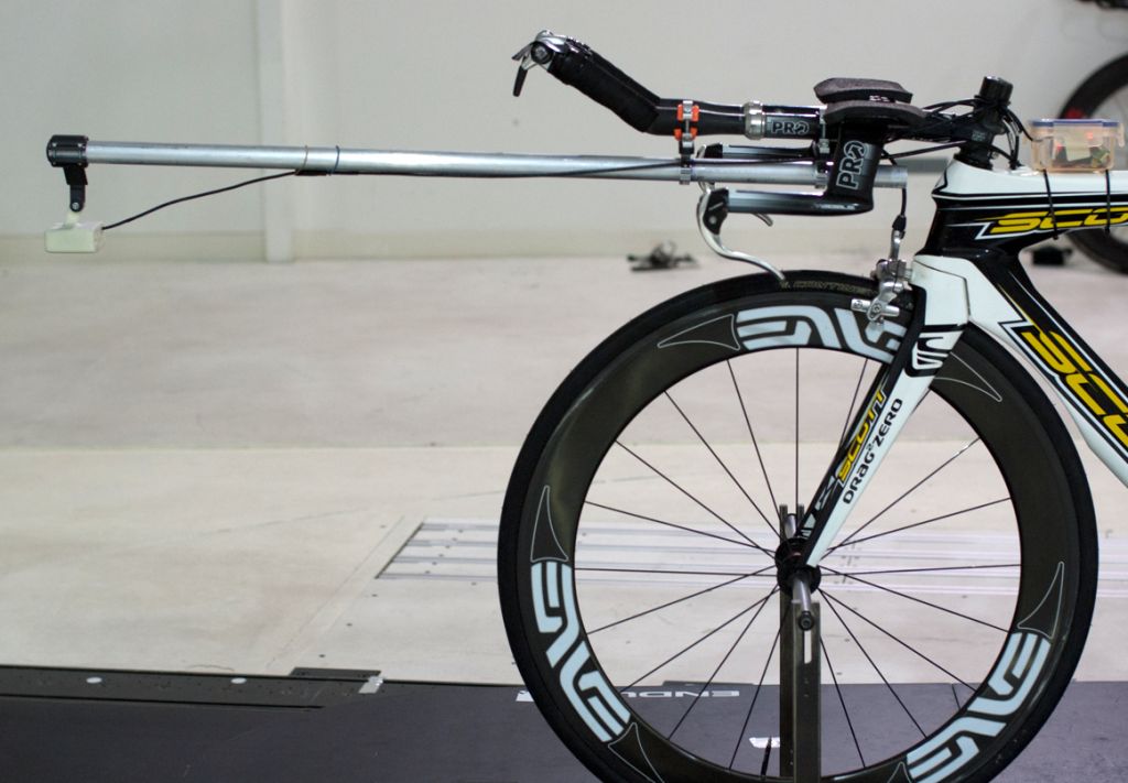
Our own wind tunnel tests confirm this effect (figure 2). Even one metre in front of the bike, air speed is still reduced by 2–3%. Unfortunately, there’s no practical way to mount a sensor far enough forward to avoid this.
This isn’t unique to Aerosensor – it’s just physics. All on-bike aerodynamic devices face the same challenge. The best we can do is minimise the effect by placing the sensor as far forward as possible, then correct for it through calibration.
Figure 2
What’s the solution?
We overcome this problem by calibrating the sensor.
In still air, road speed and true airspeed are the same. By comparing road speed to the sensor’s measured airspeed, we can calculate a calibration factor that scales the reading back to freestream conditions.
As long as the rider position and setup remain unchanged, this calibration factor will also stay constant.