3. Select the device you want to connect to. Note: it is worth keeping a note of the Device ID for your Aerosensor and Aerobody for your records, especially if you are a coach and have multiple devices for your riders.
Pass-pairing
Pass-pairing is where ACS transmits the power meter and speed sensor ANT+ connection details to Aerosensor, allowing it to connect to them directly.
For this to work the Garmin unit should already be paired with the ANT+ sensors you are using.
Note that Aerosensor requires a power meter (PWR) AND EITHER a speed sensor (SPD) OR speed + cadence sensor (BSC).
The CIQ app should automatically pass on the sensor connections to Aerosensor. In case this does not work, or you have multiple sensors on the bike, follow these steps:
Ensure that a power meter and speed sensor are installed on the bike and paired with the Garmin. Make sure they are on by rotating the wheel and/or pedals/crank, depending on the power meter.
In the ACS menu, select “Connections”->”Pass pair” which will bring up the following screen:
3. Either select the devices individually or select the bottom “Enter to sync” button in purple above. After a short period, the status bar at the bottom of the screen should go green to show Aerosensor matches the Garmin device. Aerosensor connection status icons should go from red to green.
Aerosensor Parameters
To accurately calculate aerodynamic drag, Aerosensor requires some information about you and your bike:
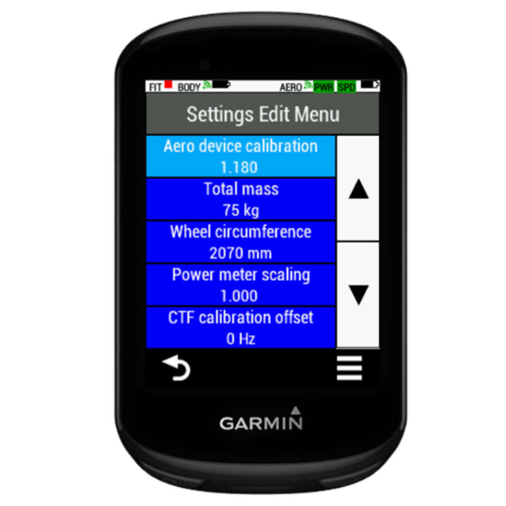
Aero device calibration: This accounts for the fact that the wind slows as it approaches the bike, so the wind speed measured by Aerosensor is always slower than the air far upstream of the bike. Start with a value of 1.4. Typically we see values beweeen 1.1 and 1.45. See ‘Quickstart’ section for more information.
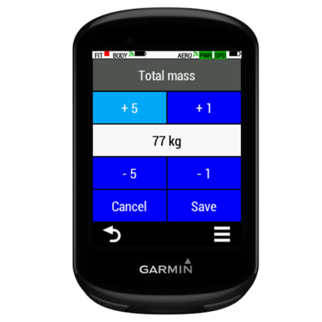
Total mass (kg): includes rider + bike + all accessories used whilst riding with Aerosensor.
Wheel Circumference (mm). If unknown, you can go into the speed sensor settings on the Garmin and you will find the wheel circumference in there once you have ridden far enough for the Garmin to calibrate against GPS.
Power meter scaling: Default value is 1.0. If using pedals or crank we need to account for drivetrain losses. A typical value would be 0.98, i.e. 2% drivetrain loss.
CTF calibration offset: Used for CTF power meters.
Time av period: This is the time period used by Aerosensor to average the CdA value, default is 30 seconds.
Reference Crr: Rolling resistance coefficient (used if known), default 0.004. For an indoor velodrome you should use 0.002 (half the road value). You can find typical crr values for a range of tyres at https://www.bicyclerollingresistance.com/
Valid speed min: minimum speed (kph) for valid CdA automatic lapping. The CdA calculation is started when you go above this speed, and stopped when you slow down below this speed. The device automatically creates laps for each CdA measurement period.
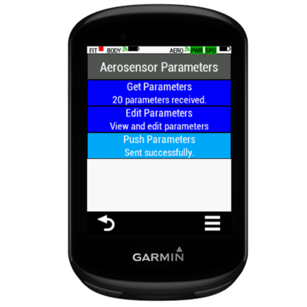
Editing Parameters:
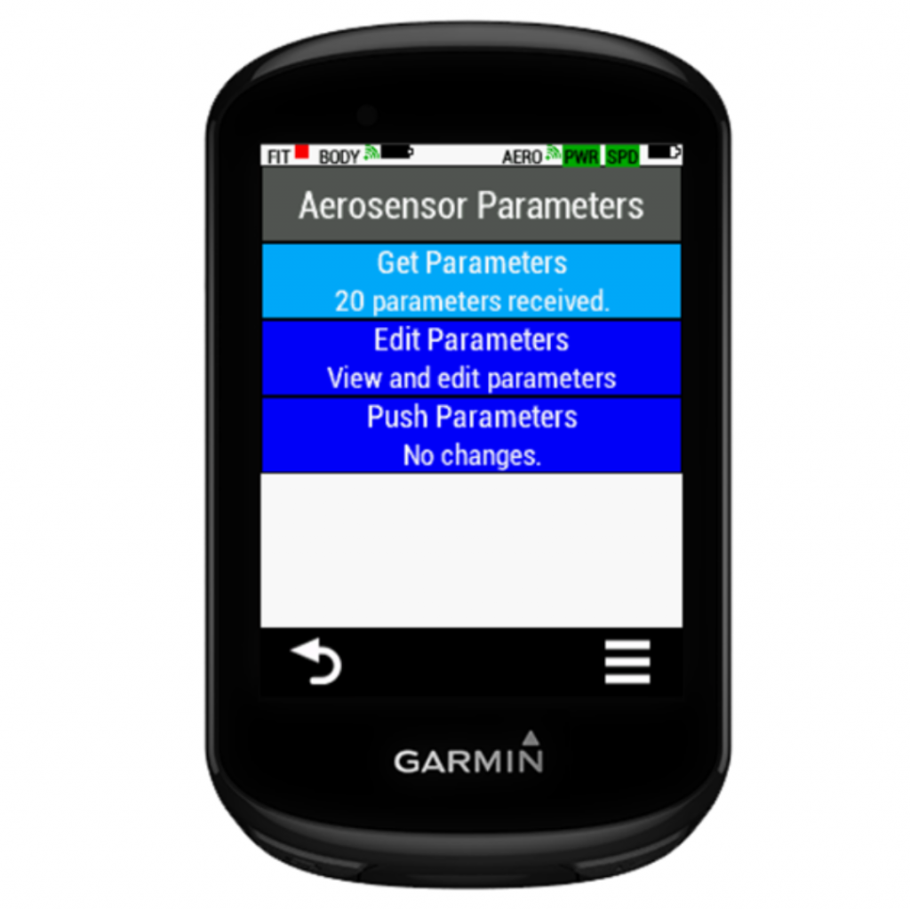
1. Go to Menu-> Aerosensor Settings-> Aerosensor
2. Ensure that the parameters have been received (“20 parameters received” under “Get Layout” button header). If not, select “Get Parameter”.
3. Select “Edit parameters” ->select setting to be edited on “Settings Edit Menu”. Use buttons to edit value. Click on “Save”.
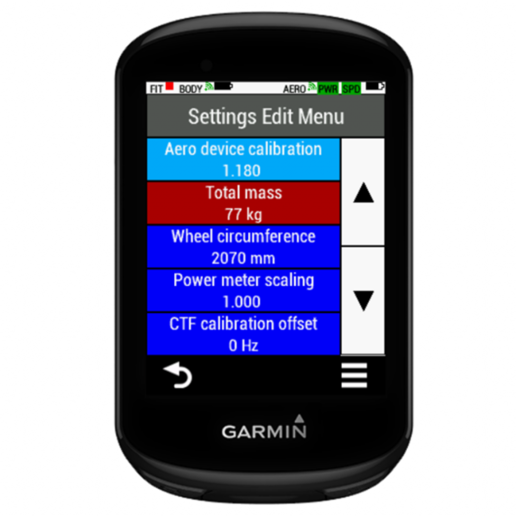
4. On return to “Settings Edit Menu” note changed parameters shown in red.
5. Return to “Aerosensor Parameters” menu.
6. Select “Push layout” to push settings to Aerosensor. If successful, “Sent successfully” will show.
It is important you check these frequently, especially total mass and wheel circumference if changing between bikes for example.
Velodrome testing – Track layout
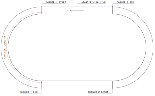
When Aerosensor is in track calculation mode it uses lap distance and speed to calculate lean angle to compensate for centre of gravity location. This only works when Aerodrome is being used. A typical track layout is shown below, of which you can input the track measurements by editing parameters directly in the CIQ app.
You can measure the track by measuring relative distance of corner start and end, using the distance markers along the track. This does not need to be very accurate – within a few meters is fine.
Measuring the track:
Measure the distance from the tapeswitch location to the start and end of each corner.
Use these to calculate the total distance of the two straight sections.
Corner length = track length – total straight lengths
Corner radius = corner length / pi
Transition length is the distance it takes for the rider to transition from the straight to the corner. Typical value is 10m.
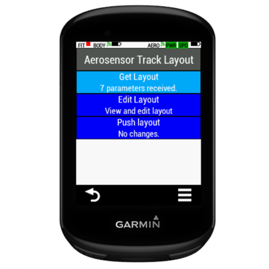
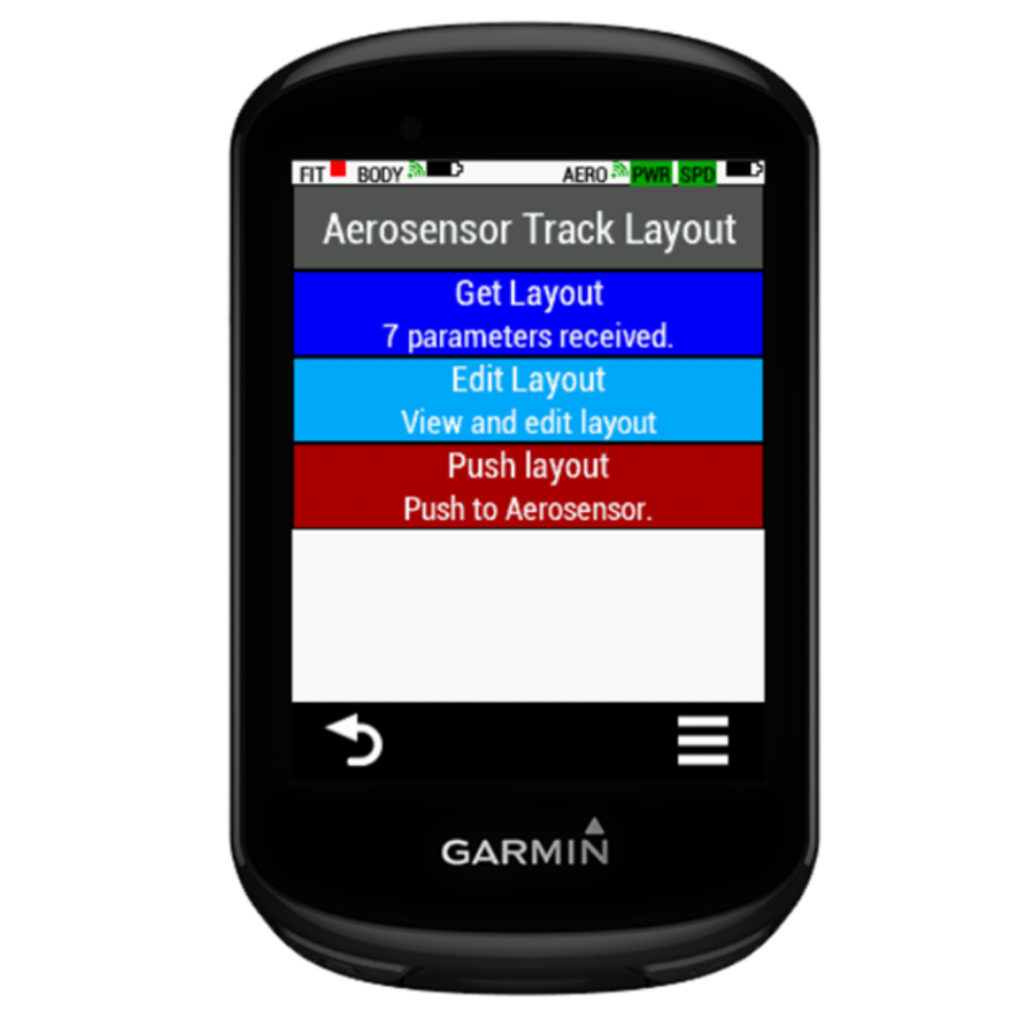
1. Go to Menu-> Aerosensor Settings->Track. and ensure that the parameters have been received. If not, select "Get Layout".
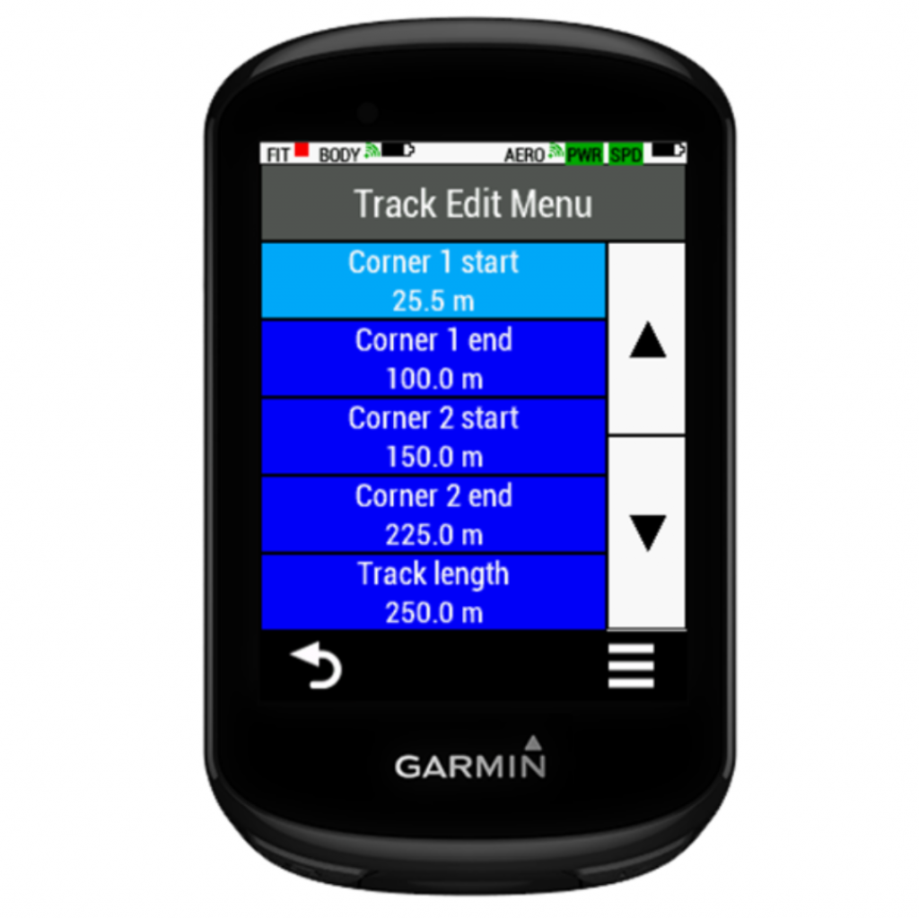
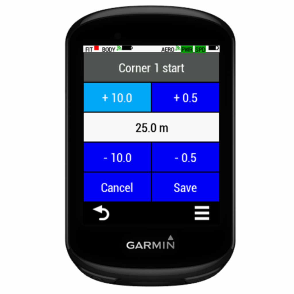
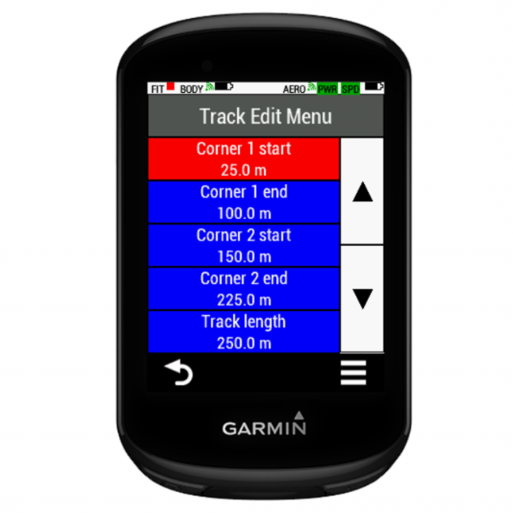
Select “Edit layout” and select setting to be edited on "Track Edit Menu".
3. Use buttons to edit value and click on "Save".
4. On return to “Track Edit Menu” note changed parameters shown in red.
5. Return to “Aerosensor Track Layout” menu.
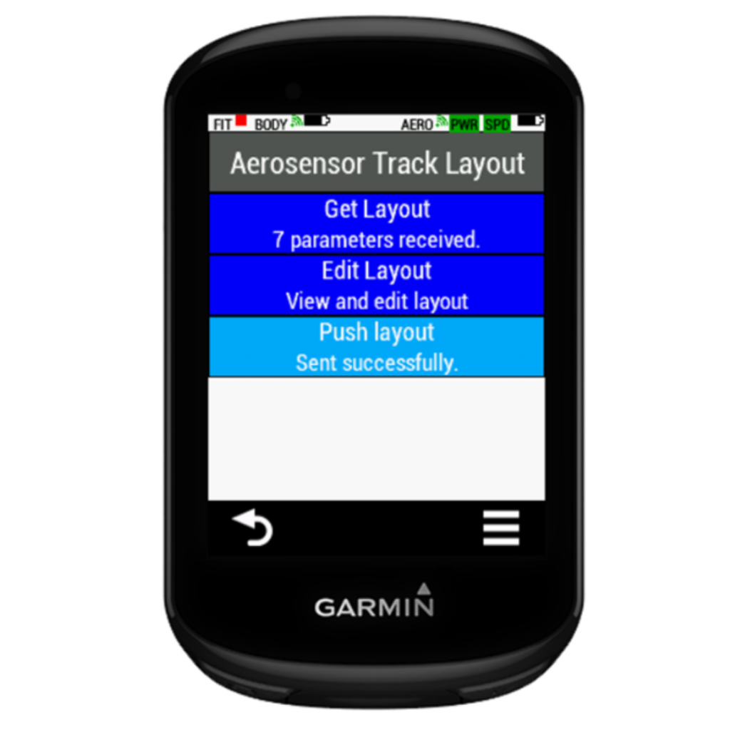
6. Select “Push layout” to push settings to Aerosensor. If successful, “Sent successfully” will show.
Velodrome testing – Calculation mode
At the velodrome Aerosensor can ignore the barometer, since elevation is roughly constant, and should use the track map. If the track map is not known, or Aerodrome is not available, you can use the trackless mode.
To use Velodrome mode:
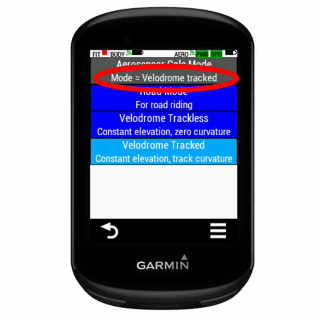
Go to Menu-> Aerosensor Settings->Calculation Mode.
Select the model you require:
Road For road riding.
Velodrome Trackless Assumes constant elevation but ignores track layout. This is for when you are not using a lap trigger (Aerodrome) or the track layout is unknown.
Velodrome Tracked Assumes constant elevation AND uses the track layout. This is for when you are using Aerodrome and know the track layout, as entered in ‘Aerosensor Settings->Track’.
Wait until the mode changes as required, in the menu heading.
Screen sequence shown below:
Aerosensor demo mode
This is for diagnostic purposes and can generally be ignored.
Aerosensor information
Go to Menu -> Aerosensor settings -> about
Here you can see information about your Aerosensor device, including battery level, firmware version and serial number. Battery voltage is also included as it is useful for diagnostic purposes.
2 Responses
Hi, first attempt robuste my aerosensor today. All sensors paired with my Garmin and reading correctly. When I entered the app I could see power numbers but all other fields reading zero. Aerosensor was connected. Found the pass pairing screen. Power meter correct. In the edge column SPD #0 Closed. In the Aerosensor column SPD #0 Searching. At the bottom of this screen „Head unit not tracking. setup head unit first“.
I have no idea what is missing and can’t find any mention of this in your documentation.
Thanks,
Julian
Hi Julian,
Sorry you are struggling. I think we have dealt with this already but for specific issues please email our support team at support@aerosensor.tech
Hope you get up and running soon!
Barney